The shear wave velocity of a soil layer is an important parameter reflecting the dynamic characteristics of the soil. It reflects the stiffness characteristics of the soil layer and has a significant influence on the ground motion parameters of a site, so the testing and estimation of shear wave velocity is an important task.
Shear wave velocity is one of the essential parameters in current seismic safety evaluation of engineering sites and seismic microzonation work. China's current seismic code for buildings, technical specification for seismic safety evaluation of engineering sites, code for geotechnical investigation, code for dynamic characteristics testing of foundations, etc., all stipulate the use of shear wave velocity data of soil layers in the calculation of geotechnical elastic parameters, calculation of foundation stiffness and damping ratio, classification of site categories, calculation of predominant period of site foundations, and discrimination of sand liquefaction. Therefore, scientific research related to shear wave velocity and its testing has important practical engineering significance.

For offshore structures, such as offshore oil platforms and offshore wind turbines, understanding the dynamic characteristics of foundation soil is of great significance. Taking offshore oil platforms as an example, they belong to Class A structures, and the Code for Seismic Design of Structures requires seismic design, in which the evaluation of soil dynamic characteristics at the platform site is an indispensable component. In the evaluation of soil dynamic characteristics at platform sites, shear wave velocity is a very important soil dynamic index that provides a basis for seismic safety evaluation. Shear wave velocity testing can be carried out through in-situ testing in the field and wave velocity testing of retrieved soil samples in the laboratory.
At present, there are mainly four commonly used offshore geotechnical wave velocity testing methods in European and American countries:
◆ Seismic cone penetration test
◆ Seismic flat dilatometer test
◆ PS wave velocity logging
◆ Bender element test
1. Seismic cone penetration test
Seismic CPT or SCPT

SCPT is a brand-new in-situ testing technology that combines CPT testing with downhole field wave velocity testing, providing an efficient, reliable, and economical wave velocity testing method to determine the shear stiffness and modulus information of soil layers. In SCPT, a seismic wave sensor is embedded in the cone penetration probe. During pauses in the cone penetration process, the operator uses the sledgehammer striking plate method on the ground to excite the dominant shear wave, uses a trigger to determine the excitation moment and trigger the acquisition instrument to collect seismic wave signals, and then immediately continues cone penetration and repeats the above shear wave signal acquisition at the next depth, repeating this until the required depth is reached.
The seismic cone penetration system (SCPT) has been proven to be a very effective tool for determining low-strain in-situ compression (P) and shear (S) velocities. P-wave and S-wave velocities are directly related to the Poisson's ratio elastic constants, shear modulus, bulk modulus, and Young's modulus of the soil. Accurate recording of the arrival times of P-waves and S-waves from the recorded time series is crucial for accurately evaluating seismic wave velocities.
Seismic CPT detection is controlled by a seismic adapter connected to a 10 cm2 or 15 cm2 CPT(U) probe. The adapter is designed so that the seismic sensor records the low-strain seismic disturbance response of the soil profile.
In SCPT testing, there are usually two types of sensors: velocity (i.e., geophones) and acceleration (i.e., accelerometers). To simplify data acquisition, all hardware and software components are designed to run with a laptop connected to a "signal conditioning system" rather than a traditional seismograph. CPT data are recorded by the GME data acquisition unit and further processed by the data acquisition software CPTest installed on the computer. The signal-conditioned seismic data are A/D converted by a PCMCIA card and then processed by SC(1-15)-DAC™ software. The SCPT system can be expanded to 15 channels (30 channels if two A/D boards are used), but generally uniaxial (SC1-DAC), triaxial (SC3-DAC), and true-interval six-channel (SC6-DAA) systems are used.

In geotechnical engineering design, another important use of shear wave velocity evaluation is soil liquefaction assessment. Since shear wave velocity is affected by many variables that influence liquefaction (such as porosity, soil density, confining stress, stress change history, and geological age), it is an excellent liquefaction index.
2. Seismic flat dilatometer test
SDMT

The seismic flat dilatometer (SDMT) combines the features of the traditional dilatometer DMT (Marchetti 1980) with the measurement function of seismic shear wave velocity VS. It was originally designed for research and has gradually developed into a major product in the in-situ testing market. The seismic wave velocity module consists of two receiving units installed at one end of the blade at a spacing of 0.5 m to measure the shear wave velocity Vs. From Vs, the micro-strain shear modulus (stiffness) Go can be derived.
SDMT provides users with a fast, accurate, simple, and economical Vs profile (with Vs repeatability as high as 1-2%).


The "two receivers/true interval" structural feature of the seismic flat dilatometer avoids the situation in conventional single-receiver wave velocity measurement where the first-arrival time may coincide with the false interval time. The two receivers measure simultaneously and receive the waveform generated by the same vibration, so there is no need to analyze other data, which also avoids interference from continuous multiple waves. This design gives SDMT very good repeatability when measuring shear wave velocity!
The test seismic source is generated by a swinging heavy hammer striking a steel base parallel to the ground surface. Of course, this base must be subjected to sufficient vertical pressure to ensure completely firm contact with the ground surface. The longitudinal coordinate of the base must be parallel to the coordinates of the receivers, which can reduce errors and maximize the sensitivity of shear wave velocity testing.
The shear wave velocity Vs is obtained by a formula, that is, the difference in distance between the two receivers and the seismic source divided by the time difference between the two receivers receiving the same waveform.
Vs can be used to derive the initial shear modulus Go. Combining the Go value from SDMT and the one-dimensional (1D) modulus M obtained from DMT is very helpful for establishing the G-Gamma modulus degradation curve.
The shear wave velocity Vs is tested at depth intervals of 0.5 m.

Nowadays, Vs is increasingly used in investigation and design, and SDMT has become one of the mainstream methods in international in-situ testing.
3. PS wave velocity logging
The suspended probe used in PS wave velocity logging is a low-frequency acoustic probe designed to measure compression wave and shear wave velocities in soil and soft rock layers. It uses indirect excitation rather than mode conversion in traditional acoustic waves, and can obtain high-resolution P-wave and S-wave data in water-filled boreholes up to 600 m deep.

The PS suspension probe contains a uniquely designed high-power seismic source and two receivers separated by an acoustic damping tube. When acquiring data, the probe stops at a set depth, and the seismic source is triggered by ground control. The trigger causes a controlled solenoid arranged along the borehole axis to strike in sequence a plate on the opposite side of the probe, establishing a pressure couple in the surrounding fluid. The resulting fluid movement generates a tube wave at the borehole wall whose velocity is close to the shear wave velocity of the formation, accompanied by a compression wave. When the wave propagates parallel to the borehole axis, it causes corresponding flow motion, which is detected by two moderately buoyant three-component hydrophones, thereby directly measuring the wave velocity. As in conventional seismic data acquisition, the operating software also includes stacking and filtering techniques.

4. Bender element test

Because of its simplicity, low cost, and non-destructive nature, the bender element test has been widely used over the past decade and is currently the most commonly used laboratory method for testing shear wave velocity.
The complete bender element system includes bender element inserts, matching base and specimen cap, signal conditioning and controller, and data acquisition device.
Among these, the bender element is the most important part of the bender element system. It is made of piezoelectric ceramic bimorphs, with a movable shim made of metal such as nickel placed between two piezoelectric wafers, bonded together to form a whole. Generally, the material of the piezoelectric device is lead zirconate titanate (Pb(Ti.Zr)O3), abbreviated as PZT. When one end of the bimorph is subjected to an excitation voltage, due to the piezoelectric effect, one ceramic piezoelectric wafer stretches and the other compresses, ultimately producing bending in the entire element; similarly, when one end of the bimorph is subjected to bending deformation, due to the inverse piezoelectric effect, a voltage is generated at the other end of the wafer.
Using this characteristic of the bender element, the bender element system consists of two separate piezoelectric ceramic bender elements, which are placed at both ends of the soil to be tested, one as the excitation element and the other as the receiving element. Each bender element is a cantilever structure, fixed at one end and free at the other, with the free end inserted into the soil being tested. A voltage is applied to the fixed end of either bender element installed at the top or bottom of the specimen, and the free end of the bender element will produce lateral deformation, generating a shear wave signal and disturbing the soil. This disturbance propagates in the soil in the form of a wave. When this disturbance propagates to the other end of the soil, the receiving bender element at that end converts this vibration into an electrical signal, thereby receiving the shear wave signal. In this way, the shear wave can be made to propagate in the soil being tested and the input and output signals can be obtained.
The above-mentioned bender element inserts are connected to the specimen cap of the matching base. The base and specimen cap can fully restrain the fixed end of the bender element, provide high axial stiffness, minimize the influence of axial load, and allow the lateral deformation of the bender element to fully enter the soil being tested.
At the same time, both bender elements are connected to the signal conditioning and controller, which can amplify the received electrical signal so that the input and output signals can be recorded more clearly. Finally, it is connected to the data acquisition device, and the data acquisition and control card in the signal controller saves and displays both the electrical signal exciting the bender element and the electrical signal received by the bender element in the data acquisition device.
The maximum strain amplitude of the shear wave excited by the bender element is on the order of 10-5-10-7. In geotechnical engineering, the material deformation can be considered to be in the elastic stage, and the propagating shear wave is an elastic wave. Based on the above introduction to the bender element system, the basic principle of using bender elements to measure soil wave velocity is to obtain the shear wave propagation velocity in the soil by dividing the propagation distance of the shear wave in the soil by the propagation time. It is a test with a very clear and simple principle.
University-Industry Collaboration | Shanghai Yuanyang Chairman Liu Zhongchi and Delegation Visit Nanjing Tech University for Exchange
下一篇Shanghai Jiuzhuo Equipment and Product Release 04 | HP-420EV High-Pressure Grouting Pump

2024-09-29 13335 0

2024-09-20 13336 0

2024-09-20 13180 0

2024-09-19 12457 0

Lize City Air Terminal Underground Main Structure Nearing Completion: Maximum Transfer Walk Under 4 Minutes After Operation

Anti-seepage Curtain for Main Lock Pit of CSCEC Port Shenqiu Double-Line Lock Project Completed on Schedule

All Pile Foundations Completed on Quanzhou Baiqi Channel

Hainan Upgrades Housing and Municipal Infrastructure
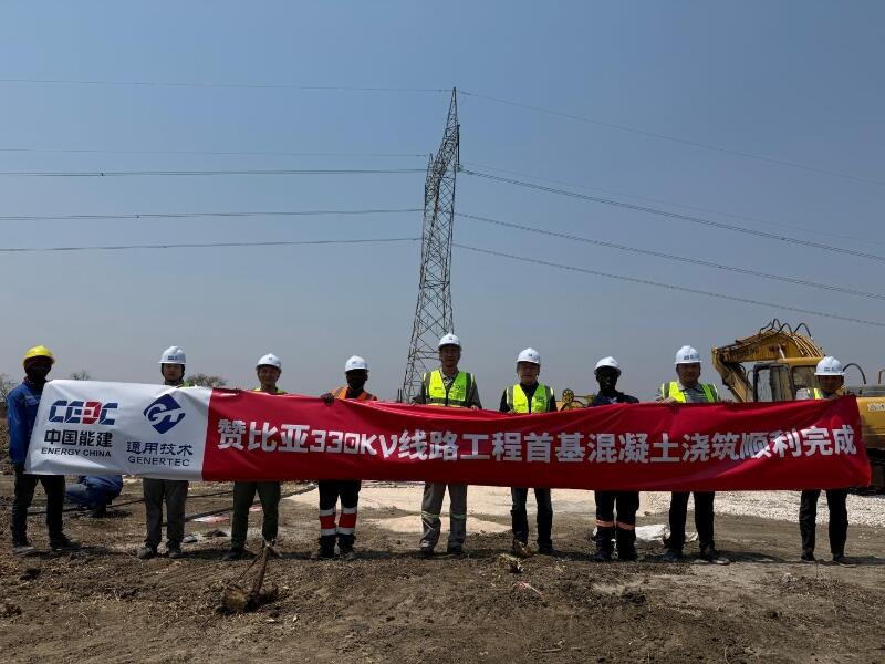
First Foundation Concrete Pour Successfully Completed for Zambia Kafue West–Muzuma 330kV Transmission Line EPC Project
Hot News

评论 (0)